
Tornado Structure, Intensity Limits and
Intensity Prediction
( May 2013)
Index
Summary
Part 1:
Tornado Structure and Wind Speed
 1.0 Introduction: The transformation of
atmospheric internal energy into tornado wind speed
1.0 Introduction: The transformation of
atmospheric internal energy into tornado wind speed
1.1 Rare miniature
whirlwind occurring in warm, clear
weather over a calm, cool lake
1.2 The structure of this strange, tiny whirlwind. Reasons why it is not a heat engine
1.3 An alternative explanation: The mini-vortex flow involves
an isentropic speed-up
1.4 A tentative sequence of events for the evolution of the
mini-vortex
Conclusions: Part I
Part 2.
Tornado Dynamics , Intensity
Limits and Intensity Prediction
2.1 Vortex features in general
2.2 Vortex motions: The Rankine Combined Vortex
2.3 The source of the rotation needed in the vortex core
2.4 The driving pressure difference and ‘throughflow’ or mass
flow rate of the tornado
2.5 Other types of tornado- like vortices
2.6 Satellite vortices, ‘sub- vortices’ or ‘suction’ vortices
2.7 Summary of the main tornado features.
2.8 A method of estimating tornado wind intensity limits from
air mass humidity
2.9 A unifying vortex element: The Flow
Condensation Discontinuity
3.0 Conclusions
Summary
 Tornados are the most violent wind storms
known, sometimes reaching wind speeds of around 250 to 300 mph. ( 112 to 134 m/s) [1]. However, there seems to be no compelling
theoretical reason why they shouldn’t continue
to increase in speed right up to
the sonic speed of around 700
mph. ( 313 m/s). Fortunately for us, they don’t. So the question arises: What limits tornado
wind intensity to less than 300 mph?
Tornados are the most violent wind storms
known, sometimes reaching wind speeds of around 250 to 300 mph. ( 112 to 134 m/s) [1]. However, there seems to be no compelling
theoretical reason why they shouldn’t continue
to increase in speed right up to
the sonic speed of around 700
mph. ( 313 m/s). Fortunately for us, they don’t. So the question arises: What limits tornado
wind intensity to less than 300 mph?
Tornadoes usually
are accompanied by, or grow out of, violent thunderstorm clouds whose
complexity makes it very difficult to know where to start for an adequate
understanding of their structure and mechanism. In addition, tornadoes are
seemingly a composite of two different types of air flows having different flow
properties--- a small central core of rotating fluid is smoothly surrounded by
a much larger area of circulating but non-rotating fluid, yet all the while the
tornado somehow maintains a unified continuous flow system through the two
different types of air flow, from inflow at ground level to outflow in the
parent storm cloud above. It is quite puzzling.
 However, a fortuitous observation of a
very simple, rare, mini- vortex over a calm, cool lake in fine weather
in Mont Tremblant Provincial Park, north of Montreal, points to one
unexpected feature, namely that the high
vortex swirl velocities are apparently produced by only small temperature changes of
a few degrees in an adiabatic/isentropic
vortex inflow process, rather than by the
inefficient heat engine process sometimes proposed, and this conclusion should apply to full scale tornadoes as
well.
However, a fortuitous observation of a
very simple, rare, mini- vortex over a calm, cool lake in fine weather
in Mont Tremblant Provincial Park, north of Montreal, points to one
unexpected feature, namely that the high
vortex swirl velocities are apparently produced by only small temperature changes of
a few degrees in an adiabatic/isentropic
vortex inflow process, rather than by the
inefficient heat engine process sometimes proposed, and this conclusion should apply to full scale tornadoes as
well.
Three new
insights will be the subject of this Website. The first is that the main speed-up process in a tornado may be
a clear air, isentropic/adiabatic
transformation, in which a small amount of the internal heat of the air flow is transformed into the
observed high vortex wind speed. Second, this high speed- up, isentropic flow
process is terminated by the formation
of the tornado funnel cloud which releases latent heat of condensation into the
vortex as it forms and thereby stops the high speed- up, isentropic phase completely and allows a heat engine
process to take over. This presents the possibility of
predicting the general level of tornado intensity on a given day from the
relative humidity of the air masses involved. Third
, this same condensation discontinuity in the flow also introduces
fluid rotation directly into the core where it is needed to stabilize the
vortex.
We should note
that an enormous amount of data and theoretical insight already exists on
tornado structure and dynamics, and that the new insights offered here must be
evaluated within the framework of this existing knowledge.
Part 1: Tornado Structure and
Wind Speed
1.0
Introduction: The Transformation
of Atmospheric Internal Energy into Tornado Wind Speed
![Text Box: V = [2cpΔT(ΔT/To)]1/2
(Heat engine)
V = n1/2co ( ΔT/To)1/2
(Isentropic Flow )](Section%206%20Tornado%20Structure_files/image032.png) As background to these energy transformations, and apart from the
straight line winds of ordinary weather systems, there are two principal
atmospheric physical processes that can cause the observed, localized air flow
speed up by flow expansion into the low pressure core of vortices or
whirlwinds.
As background to these energy transformations, and apart from the
straight line winds of ordinary weather systems, there are two principal
atmospheric physical processes that can cause the observed, localized air flow
speed up by flow expansion into the low pressure core of vortices or
whirlwinds.
First, there is the heat engine process in which
heat energy difference-- that is to say,
either internal heat or heat
arising from temperature differences
between adjacent atmospheric air parcels -- is converted to kinetic energy of wind flow, ½ mV2 , by a volume expansion of
low efficiency,with accompanying small flow speed increase.
Second, there is the isentropic conversion of internal heat
energy into flow speed via a
linear flow expansion which, under the action of some physical
constraint to the flow, converts internal heat energy and small, commonly
occurring, temperature and pressure differences, to large flow velocities. [In
ordinary linear flow, such a constraint could be the walls of a
converging/diverging nozzle; in free flow in the atmosphere, the constraint is
the centrifugal force acting on the curved air flow in a vortex and especially
on the walls of the funnel of a vortex].
1. The heat engine equation [7] is as follows:
V = [ 2 cp ΔT (ΔT/To) ]1/2
(1)
For example, a 1˚C
temperature drop in the warm air flowing into a vortex in the heat engine
process increases the flow speed V by 3.6 m/s.( 8 mph) [ V = [2 x 1004.6 x 1 x 1/303]1/2 = 3.6 m/s].
See Table 1, Sect. 1.3. The prevailing
temperature is taken here as 303˚ K (30˚ C) and cp is the specific heat of air at
constant pressure
2. The second possible process is the isentropic/adiabatic flow speed-up
transformation [2, 11, 22] whose equation, linking flow velocity to
expansion temperature change, is:
V = n1/2 co [1 −
T/To]1/2 = n1/2 co [ ΔT/To]1/2 (2)
In this isentropic
transformation ( Table 1, Sect.
1.3) the same 1 degree C temperature drop in the vortex
inflow will yield a wind
speed increase of 43 m/s (96 mph),
or 12 times as great as that of the
heat engine process! [V = 51/2 x 334 x [1/303]1/2 = 43 m/s] .
In this example, n , the energy
partition number, is 5 for air, co is
the local speed of sound taken as 334
m/s, and the background air temperature is taken as 303˚ K.
[Put another way equivalent way, we could also say
that : A small local pressure
differential of 11 millibars (1100
Pascals) between two points in an air mass which is suitably restrained
laterally by the centrifugal force of a
swirl, could cause an isentropic flow expansion and produce a tangential flow velocity of 43 m/s and a temperature drop in the air
of 1 degree C. ]
Our relevant question
now is: Do these processes also act in
tornadoes, and can they explain the observed tornado wind speeds and behaviour?
 Fortunately, a chance, first -hand
observation in 1987 of a rare, fine weather, mini-whirlwind in the air just
above the surface of a small lake in Parc Mont Tremblant north of
Fortunately, a chance, first -hand
observation in 1987 of a rare, fine weather, mini-whirlwind in the air just
above the surface of a small lake in Parc Mont Tremblant north of
The winds in the violent little mini-whirlwind, which lasted about
15 seconds, were estimated to be 30 -
35 m/s (67 -78 mph). The column of swirling cloud or mist was about 1.5 meter
in diameter by about 2-3 meters high. The maximum temperature difference
between lake water and the air over it was about 5˚C. The weather
that day was fine, the sky was cloudless and the wind over the lake
surface elsewhere was almost calm.
The conclusion of the analysis was
that the brief, swirling wind
speeds of about 35 m/s in the tiny whirlwind could only be explained by an isentropic conversion of
0.5 - 1 degree C of the temperature difference between the
air at the lake surface and the air 6 to
8 feet above it, into wind speed,
since this process yields the observed winds of 35m/s, whereas the heat engine process
would produce winds of only about 3.6 m/s.
In the years since 1987, much effort has been
put into applying these insights to laboratory flow devices, to the theoretical
structure of full size tornadoes in the atmosphere, and to the apparent
limitation of their wind speeds to around 135 m/s ( 300 mph).
These insights
have now led to a new general insight into tornado structure, and to a new
approach to the prediction of tornado intensity limits.
To sum up, most
intense tornadoes in the  wind speeds of less than about 90 m/s (200
mph). The expected upper limit in wind speed is usually considered to be about
130-140 m/s 290 – 316 mph) [1].
wind speeds of less than about 90 m/s (200
mph). The expected upper limit in wind speed is usually considered to be about
130-140 m/s 290 – 316 mph) [1].
However, since it is relatively easy in the laboratory to accelerate an air flow up to the sonic
limit of 313 m/s ( 700 mph) --- for example, in a converging- diverging nozzle
flow) [2, 11] --- one may wonder why tornado winds are usually held down to only about 90 m/s (200 mph) or
so.
An understanding
of this apparent tornado wind speed limit would have important practical
consequences for structural engineering, building design, insurance risk
calculations, public safety and so on.
Full scale
tornados are very complex dynamic systems; they occur associated with intense
convective storm systems and the extreme violence of their wind and weather
make the gathering of precise observational data about them a matter of
difficulty and danger. Years of intense work have yielded a great understanding
of much of their nature [1]. Yet many points are still a matter of debate.
Consequently, any new data or insights into their nature are very desirable.
Doswell and
Burgess have stated [3] that: “From a purely dynamical viewpoint, tornadoes
arise from amplification of either existing or locally produced vorticity. However,
this is a somewhat abstract framework for understanding tornadoes”. And so they
go on, instead, to discuss them from the practical standpoint of the
convective features of tornado storm cloud systems.
Here, we shall
concentrate on the physical process of the conversion of internal heat
energy of the air masses to isentropic
flow expansion, with its associated small temperature drop and large flow
speed- up, and its application to full-scale tornadoes in the atmosphere.
 1.1 Rare miniature
whirlwinds occurring in warm clear
weather on calm, cool lakes
1.1 Rare miniature
whirlwinds occurring in warm clear
weather on calm, cool lakes
These very rare, mysterious,
fine weather, tiny but violent whirlwinds first came vividly to personal
attention of the Website author, a professional meteorologist, on
It was a fine, warm sunny
morning with little or no wind. At about 11 a.m. Pauline called out in alarm at the sudden appearance
out of nowhere of a small, violently whirling, column of mist over the water in a small bay about 100 meters from our boat
and about 50 meters from the forested shoreline.
The swirling mist column was about 2 to 3
meters feet high and 1.5 meters in
diameter, centered over a circular
patch of somewhat ruffled surface
water about 8 meters in diameter. The central mist column was whirling
round and round violently, all the while emitting a hissing sound. After
about 15 seconds in the same location, the whirlwind disappeared as suddenly as it had formed,
leaving only a small, darkened, breeze-
ruffled area on the surface of the water which
then drifted away across the lake at about 10 km/hr toward the eastern
shore. This lake is shallow, not over 7 meters or so deep at the deepest spot.
An inspection of the little
bay along the north shore of the lake where the whirlwind had erupted showed no
signs of any disturbance in the water itself, which was perfectly clear right
down a meter or so to the undisturbed lake bottom. Obviously the whirl had been
in the air above the water only. The lake water temperature was cool at around
18 ˚C. The air temperature was warm at about 25˚C ( 24 to 26˚C).
This situation, with cool air at the surface and warmer air above is just the
reverse of the temperature stratification that occurs in tornados, waterspouts
and dust devils where the air is warm at the surface and cooler aloft. This
strange set of circumstances, almost completely the opposite of conditions in
storm tornadoes, naturally provoked intense curiosity. It certainly invited careful study and analysis,
especially since the weather conditions were of extreme simplicity. The violent
little whirlwind with winds estimated at 30-35 m/s ( 67 to 78 mph) had
apparently emerged suddenly ‘out of
nowhere’! How could this happen?
Further investigation soon
showed that there was only one other account in the scientific literature of a
similar phenomena occurring in
We later met with M. Bernard Bruneau, Park Warden of Mont
Tremblant Provincial Park for 24 years, who told us that he also had seen such tiny whirlwinds on the Park’s lakes, but only
on two or three occasions during his
entire career, and once on a calm stretch of a small river. All had occurred on
fine, sunny, warm, nearly windless days in late morning or shortly after
Clearly, what we had seen was
a very rare event. The weather at the
time, also, was so simple, meteorologically speaking, compared to tornadoes and
waterspouts, that it invited close scientific analysis [6]. The general situation is shown in Figures
1,2,3.

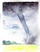
Fig. 1. Watercolour sketch of small, rare whirlwind
seen on Lac de la Fourche,
18˚ 23˚ 25˚
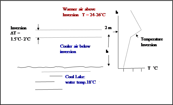
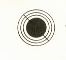
Figure 2. Estimated
Temperature profile over cool lake surface
Cool water temp. 18˚C
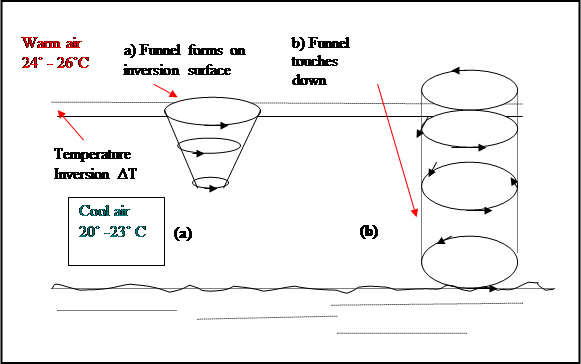
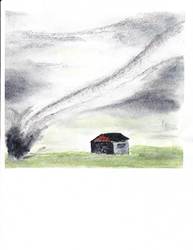
Fig. 3 Schematic cross section ( a) Incipient whirlwind (b) The fully formed vortex.
1.2 The
structure of this strange, tiny whirlwind:
Reasons why it was not a heat engine
The first conclusion of the initial study [6] was that, if the
vortex and its strong swirling winds were an atmospheric heat engine, then the
heat source must be the warm air just above the temperature inversion at a
height of about two meters above the surface of the lake.
Indeed, it has in
the past been one explanation of tornados
that they are atmospheric heat engines, driven by
convective instability between a warm
moist source at the ground level and the upper atmospheres at much cooler sink
temperatures, the general temperature differential in a mature tornado thus
being about 40 - 50° C. The heat engine [ 7] is an irreversible, non-isentropic flow, where the
relationship between velocity V, and thermodynamic quantities of heat Q, and temperature T, is given [6,7]
by:
V = [ 2 cp
ΔT (ΔT/To) ]1/2 (1)
where cp
is the specific heat at constant
pressure ( 0.24 gram calories in air at 20C or 1004.6 J/kg), ΔT = To − Ti
is the temperature drop from source to sink, and ΔT/To = ( To − T)/To = 1 − T/To is the
thermodynamic efficiency of the heat engine as required by the 2nd
law of thermodynamics, which limits the amount of work that can be extracted
from any given heat input. (The work done ( dW = pdv) enters through the
expansion of the air as it flows into
the lower pressure of the vortex core ).
Now in the case of the mini-whirlwind,
observed in 1987, the heat difference
ΔT between the heat source in the warm air above the
inversion over the lake and the heat
sink in the core of the vortex at the lake surface could not be more than the
temperature difference between water temperature and air temperature which was
at most about 7˚C, and more likely
was on average less than half that value, 3.5˚C.
In that case, the
resulting winds from Equation 1 for a heat engine operating at a ΔT of 3.5
degrees would be only about 9 m/s, far below the 30 to 35 m/s observed. We
cannot therefore explain this cool-lake whirlwind as a heat engine transforming
heat energy into wind speed, that is, by transforming potential energy of
heat into kinetic energy of wind speed. It appeared that some other mechanism to
explain the high swirling wind speeds must be sought.
1.3 An
Alternative Explanation: The Mini-vortex Flow Involves an Isentropic Speed-up
Turning from the
heat engine model, we next examined the isentropic/adiabatic
flow expansion [22] and its accompanying transformation of internal heat energy
ΔQ into kinetic energy ( ½ mV2) and flow velocity V. Since the expansion transformation is
isentropic, the heat transformation is wholly internal, no heat is passed to or
from the environment and much large flow velocities emerge.
These isentropic
transformations of internal energy into flow velocity, with no heat flow into
or out of the system, are given by [2,11] the following equation:
V = n1/2 co [1 −
T/To]1/2 = n1/2 co [ ΔT/To]1/2 (2)
.
This is derived as
follows: We start with the energy equation in terms of actual wave speed c,
static wave speed co,
temperature T, flow velocity V, and n, the number of ways the energy of the air
is divided. ( n also equals 2/ (k − 1)
where k is the ratio of specific heats cp/cv, and has the value of 1.4 for air.) As is usual in flow theory, we consider unit
mass of fluid, so that m (= 1) does not
appear explicitly in the energy equation which is as follows:
c2 = co2 − V2 /n
c2/co2 =
1 − V2 / nco2
If we now further
restrict the adiabatic case to reversible flow, we have the convenient
isentropic relations [10]
c2/co2 =(
p/po)2/n+2 = ( ρ/ ρo)2/n = T/To
and so
T/To = 1 − V2
/n co2 ,, whence
we have Eqn. 2 above, i.e.
V = n1/2 co [1 −
T/To]1/2 = n1/2 co [ ΔT/To]1/2 (3)
which gives the
relationship between increased flow velocity V and ΔT, the temperature
drop during the isentropic expansion.
Table 4 gives the computed values of V for a range of temperature
changes ΔT, calculated from Equation 2, taking n = 5, co = 334 m/s, and To = 303˚K
( 30˚C).
Table 1
Flow Velocity Versus
Temperature Change (a) in a Heat Engine and (b)
in Isentropic (adiabatic, reversible)
Expansion of Air Flow
Cp =
1004.64 = 0.24 x 4186 J/kg/deg C
To = 303 deg K (30˚ C) Heat
Engine Process Isentropic Process
co =
334 m/s Velocity Increase (m/s and
mph) Velocity
Increase (m/s and mph)
ΔT To
T1 V = [ 2 cp
ΔT ( 1 – To/T1)]1/2 V = n1/2 co [ 1 – T1/To]1/2
m/s mph m/s mph
0.5˚ 303K 302.5˚K 1.29 2.9 30.3 67.9
1 “ 302˚ 2.58 5.76 42.9 96.0
2 “ 301 5.15 11.5 60.7 135.7
3 “ 300 7.73 17.3 74.3 166.2
3.5 “ 299.5 9.03 20.2 80.2 179.4
4 “ 299 10.3 23.0 85.8 192
5
298
12.9 28.8 95.9 214.6
10 “ 293 25.8 57.6 135.6 303.4
Note 1: Values in blue are for the observed cool
lake vortex wind speeds corresponding to various possible temperature drops
2. Conversion
factor: m/s x 2.237 = mph
It is apparent
that isentropic flow velocity
transformations can easily account for the magnitude of the winds
in this tiny, intense vortex ( 35 m/s) as arising from the available temperature differences (1 to 3 degC) that
exist in the inversion over the cool
lake surface. Table 4 shows that
even a temperature differential at the inversion level of only 0.5˚C
transforms or corresponds to a flow velocity of 30 m/s or 68.1mph, while a 1˚C
temperature differential could produce a wind speed of 43 m/s (96mph).
Therefore
we can now apparently relate the Lac de la Fourche observed wind speeds of 30
to 35 m/s to a small temperature difference of only about 0.5 to 1˚ C in the
temperature inversion over the lake by invoking an isentropic energy transformation.
If this mechanism
acts in one vortex in the atmosphere, it ought to be able to act at other similar
atmospheric vortices large or small, and so we may also have an explanation
that should be relevant to tornados and
waterspouts as well. The isentropic expansion transformation of
internal heat energy corresponding to a flow’s
temperature drop of only 1 to 3 ˚
C--- a commonplace occurrence in the
atmosphere-- will account for the
maximum observed wind speeds in most tornadoes (Table 1). 42.9 m/s -74.3 m/s ( 96 to 166 mph0. A difference of 5˚ C, upon isentropic
flow expansion would give 95.9 m/s (214 mph) equivalent to most intense
tornadoes.
We have shown that the isentropic
transformation of temperature to flow velocity can explain the intensity of the
observed winds in the mini-vortex over the cool lake and that the heat engine
process can not. We therefore reasonably
have concluded that the actual process at work is the isentropic one.
But, we have not examined the precise physical
reasons why this should be so. We shall
not attempt to do this here in a detailed or rigorous way. But, we point out
the effect of centrifugal force and acceleration generated by the swirling
circular flow.
For example, in
the linear flow of air through a converging nozzle [2,] the air accelerates
isentropically because of the reduction in cross sectional area of the nozzle. Put another way, if the air
motions are restricted in two directions - say, the x and y directions - the flow must accelerate in the flow or z-
direction in order to conserve the mass flow constancy under a fixed driving
pressure differential.
In the case of a
flow in a vortex, the centrifugal force set up by the circulation and/or
rotation plays the part of the solid wall of the converging duct of the nozzle;
it acts to restrain the direction of expansion and to permit an acceleration in
the unrestrained direction, which is now in the tangential flow direction.
This centrifugal
force effect acts in both the isentropic and the heat engine cases, since the
air flows in circular motion in both cases, but with different velocity increases---
large in the isentropic case and much smaller in the heat engine case.
Note. While we have looked at this isentropic flow
process as a transformation of internal heat into flow speed increase and
temperature drop by linear expansion, we could just as validly have presented
it as a conversion of pressure differences to flow speed, since from the
isentropic equations above, we have
ΔT = To [ V2 /nco2] and
Δp = po [ 1 – (T/T0‑)n+2/n
] = po [ 1 - (V2/nco2)n+2/n
]
which links
pressure differences Δp to temperature differences ΔT and isentropic flow velocity V.
1.4 A tentative sequence of events for the evolution of the mini-vortex.
The available
data on this mini-vortex suggest that the possible life cycle evolution is
somewhat as follows:
1. With warm air
from the land draining out on top of the shallow layer of cool air over the lake surface in the early morning, a
temperature inversion forms and persists from shortly after dawn until mid -
morning. (Figure 4 (A and C)).This inversion is topped at about 6 to 10 feet
above the lake surface.
2. Late morning
of a calm, sunny, warm day would be the time when the temperature inversion
begins to weaken as the sun heats up the cool air at and above the lake surface. The cool air over the lake thus begins to approach the
stability point where normal convective mixing of surface air with air above
can resume over the lake, just as it
already has over the land since after
sunrise ( Figure 4 C).
3. Any light breeze
or puff of wind along the shoreline in these nearly calm conditions could set
up a weak wind shear which will cause a slow counter swirl to form out in the
air over the lake in any small bay along the shore. This swirl will be in both
the warm air above the temperature inversion and in the cool surface air below
it. The acceleration accompanying the
curved flow of the weak swirl in the air initiates a small pressure and
temperature drop.
V = n1/2co [ 1 – T/To]1/2
= n1/2co [ 1 –
(p/po)2/7]1/2
3. The angular
momentum initiated by the wind shear along the shore is conserved as the air in
the swirl flows spirally in towards the centre of the swirl in the bay. The
flow speed towards the centre of the swirl must therefore also increase because
of this conservation effect and the speed up further deepens the swirl’s
pressure drop.
4. In most cases, with weak swirling motion the
force of viscosity will act to weaken and perhaps dissipate any incipient
vortex. But, in cases where the vortex occurrence also
coincides with the cycle of restoration
of normal convective motions over the
lake in the late morning, then the cooling of the warm air flowing into the vortex will erase the inversion and the stability, and so can
restore the lapse rate in the vortex core to the normal convective value. This would permit vertical convective flow to
resume over the lake --- but only up through the vortex itself, where the expansive cooling has erased the warm
inversion cap.
Thus the vortex,
occurring at the right time of the surface air heating cycle over the lake can
locally readjust the lapse rate in its funnel
to the normal convective mixing value. The convective upwards flow then
resumes- but only up through the vortex funnel (Figure 4 D).
This is somewhat
analogous to the situation where water in a sink drains out through the drain
hole under the force of gravity. In the case of the lake whirlwind, the air
over the lake surface can locally ‘drain upward’, so to speak, through the
vortex funnel under the force of convective buoyancy.
Fig. 4.Temperature inversion prevents
convection (A and C), while ‘Erasure’ of inversion in vortex restores
convection (D).
Conclusions: Part I
The study of the
mini-whirlwind has led to the conclusion that the principal wind speed up
process in the vortex is an adiabatic –isentropic linear expansion involving a small
temperature, pressure and density drop accompanied by a very large wind flow
increase.
The necessary
initial swirl is set up by wind shear along the lake shore topography, and at a
low level tempersture inversion over the lake, where the whirlwind formed.
The rarity of the
phenomenon is due to the necessity to match all the elements of the whirlwind
to the ‘window in time’ in the late morning when the restraining temperature inversion over the lake is not
quite at the breakup stage in the daily heating cycle, that is to say at the point in time when
the normal daytime vertical convective
motions can resume. If the conditions do all match, then the swirl breaks the
inversion cap in the vortex core and an upward convective flow can suddenly
begin, channeled up through the vortex funnel to exit into the free air above
the inversion.
The mechanism of
isentropic flow speed up should apply to all whirlwinds, large and small. The
inversion breakdown channeling a convective flow up through a vortex core may also apply to tornado funnel
cloud formation on a cool dome’s inversion surface at a storm
cloud’s base.
We now turn in
Part 2 to the application of these insights to tornadoes.
Part 2. Tornado Dynamics, Intensity Limits and Intensity Prediction
Index
2.1 Vortex features in general
2.2 Vortex motions: The Rankine Combined Vortex
2.3 The source of the rotation needed in the vortex core
2.4 The driving pressure difference and ‘throughflow’ or mass
flow rate of the tornado
2.5 Other types of tornado- like vortices
2.6 Satellite vortices, ‘sub- vortices’ or ‘suction’ vortices
2.7 Summary of the main tornado features.
2.8 A method of estimating tornado wind intensity limits from
air mass humidity
2.9 A unifying vortex element: the flow condensation
discontinuity
2.10 Conclusions
2.1 Vortex
Features in General.
 In general, atmospheric vortices appear to
start as fluid rotation arising in a wind shear zone along a temperature discontinuity, in conflicting shearing flows inside a convective storm cloud, or
from intersecting air outflows of different flow directions beneath a storm
cloud [8,9]. Once the swirl of a vortex
starts, the pressure in the swirl falls because of the acceleration and
pressure force distribution in the curved air flow. The air flows spirally
inwards toward the lower pressure at the vortex centre. At the same time, the conservation of angular
momentum requires a speed up in the air flowing into the vortex at this ever
diminishing radius. This angular momentum speed up follows from the
relationship between vortex flow velocity V, rotation rate ω, and radial
distance r from the vortex centre
In general, atmospheric vortices appear to
start as fluid rotation arising in a wind shear zone along a temperature discontinuity, in conflicting shearing flows inside a convective storm cloud, or
from intersecting air outflows of different flow directions beneath a storm
cloud [8,9]. Once the swirl of a vortex
starts, the pressure in the swirl falls because of the acceleration and
pressure force distribution in the curved air flow. The air flows spirally
inwards toward the lower pressure at the vortex centre. At the same time, the conservation of angular
momentum requires a speed up in the air flowing into the vortex at this ever
diminishing radius. This angular momentum speed up follows from the
relationship between vortex flow velocity V, rotation rate ω, and radial
distance r from the vortex centre
V/r =
ω = constant
whereby, as r
decreases towards the centre of the vortex,
the corresponding flow velocity V must increase to keep ω
constant.
Once the swirl is
started, it can be maintained or grow if there is a ‘throughflow’ of air driven
by some overall pressure drop from flow source at the base of the vortex to its
sink aloft, and if the rotation needed at the core can be supplied.
The following is
a brief theoretical account of vortex structure and flow dynamics:
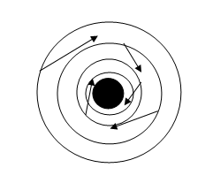
 2. 2 Vortex
Motions; The Rankine Combined Vortex
2. 2 Vortex
Motions; The Rankine Combined Vortex
A Vortex involves organized circulatory or rotary motion of a fluid (i.e. liquid or gas) in which the fluid motion is round and round about a central point or central axis. The swirling motion of water slowly draining from a sink or wash basin is an example of a vortex. The flow around the perimeter of the basin and in the main body of the water in the wash basin is circulating, but it is not technically rotating. This seems a bit contradictory, but, for example, a floating cork which has a straight index line inscribed on its top, circulates around and round with the water, but the orientation of the line inscribed on the cork acts much as the needle of a compass and remains pointing in the same direction.. While the cork and the water it is floating in certainly do circulate, they do not themselves rotate. However, near the centre of the swirling water, if there is no actual gap in the fluid, the motion is different ---there the water core rotates in a wheel-like manner so that the rotation becomes zero at the central axis.
When the flow is steady, the outer, non-rotating circulation is described mathematically as
VT r = Γ =constant
were Γ, with dimensions of angular momentum, is called the circulation, and VT is the tangential velocity at any point of radius r. An example of this type of circulatory motion is the potential vortex, often called a free vortex, in which the motion can be described by a potential velocity function φ, such that dφ/dx = V [11 12]. The circulation of the water draining from a washbasin at points well away from the centre of the basin is an example of this potential vortex motion.
On the other hand, the true rotational motion in the inner core is called ‘solid’ or ‘wheel-like’ rotation, or sometimes, a forced vortex or rectilinear vortex, and is described mathematically as
VT/r = ω
were ω is the rotation with the dimensions of frequency.
Atmospheric vortices typically consist of an outer
circulatory whirl of irrotational or potential motion enclosing a very
small inner core of solid rotation. The presence of the solid rotational core
is physically necessary because a
pure circulatory or potential
vortex would require a velocity V of infinity at the core where r = 0, and so, in nature, some adjustment is necessary.
This problem of infinity is avoided by a
core having solid-like rotation, since then the velocity drops to zero at the
central axis as required. The two flow systems 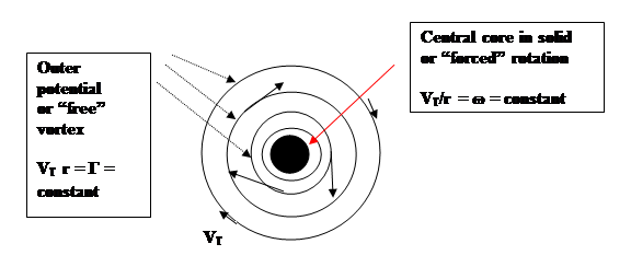 taken
together are often called a Rankine combined vortex [2,11,12 ].
taken
together are often called a Rankine combined vortex [2,11,12 ].
Figure 5. The Rankine Combined Vortex
2.3 The source of the initial rotation needed in the vortex core.
Vortex flow, with its angular momentum,
swirl, or rotational motion cannot arise
in a fluid spontaneously. As we have
stated above, it must be formed at some shear surface or fluid discontinuity in
one of several ways [1,2]. First, the
boundary layer in any fluid flow has rotation because of the action of
viscosity as the flow moves past the
bounding surface, and also in the flow past a rounded edge. Across a discontinuity of any flow velocity,
(Fig. 6) shear flow sets up small fluid vortices or fluid rotation which can
then be entrained into the body of the fluid at a fluid boundary. As we shall
discuss later, rotation can also arise from condensation of water vapour into
cloud to form the tornado funnel. This last source has the advantage that the rotation
emerges directly in the vortex core where it is essential to the vortex
stability.
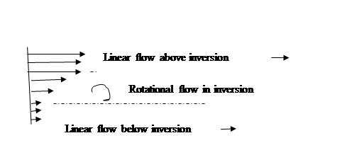
Figure 6.
Formation of small vortices in a surface of discontinuity with shear flow
In the case of
tornadoes, it appears that a principal source of the necessary initial fluid
rotational motion is often the interaction between two different outflows of
air beneath a storm cloud system as they meet and swirl at the earth’s surface. This applies in particular to interactions
with the rear cool outflow or rear flank downdraft.
A principal
source of such different cool outflows that can generate tornadoes in this
manner is the local cooling of the air beneath convective shower clouds by
shafts of falling rain, which partially
evaporate and cool the air to form what is called a ‘cool dome’ of air beneath the rain cloud [8]. These cool
domes typically have horizontal dimensions of a few kilometers. The surfaces of these cool domes are
surfaces of the vorticity or rotation that can give rise to tornadoes.
In more detail, if the air beneath the shower cloud is at less then 100%
humidity, as is usually the case, then some of the falling rain evaporates into
the air and cools is by from 1 to say 5 deg C.
The thin zone separating this dome of rain cooled air from the outside
warm air, forms the temperature discontinuity or inversion surface we have
mentioned. This temperature inversion surface (cool below, warmer aloft)
is almost horizontal at the cloud
base right beneath the cloud and slopes away to almost vertical at the leading
edge of the cool dome at the ground, out
ahead of the shower, as in a downdraft outflow.
The shear across the discontinuity surface gives rise to a vortex sheet.
As stated, two separate down flows of this rain cooled air, if and when they
intersect, can generate the starting swirl needed for a tornado.
In some cases,
tornadoes also seem to start on the surface of these sloping cool dome
inversions under the cloud base, and
then grow down from the cloud base along
the curved dome to the ground.
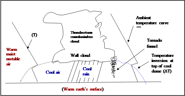
Fig. 7
Formation of a dome of cool air capped by a temperature inversion of 1
to 5 deg C beneath and out ahead of a thundershower cloud.
For completeness,
we may note that another possible cause of rotation arises from instability
waves on an atmospheric temperature inversion [12]. Such waves can become
unstable and grow to form a vortex core.
2.4 The driving pressure difference and
‘throughflow’ or mass flow rate of the
tornado
The
tornado is driven by a pressure
differnce Δp beween the ground level flow ( ‘source) and some flow exit
level in the storm cloud interior alof (‘sink’).
The mass flow rate [ m-dot = dm/dt = ρVA = constant] up through the vortex
is driven by the flow pressure
gradient −Δp between the pressure in the core at the
ground level and that in the convective storm cloud above where the funnel flow exits.
The pressure drop explanation and the tempersture drop
explanations are equivalent, since in isentropic flow, as we have shown, the flow speed-up
(+ΔV) is matched by a pressure, temperature and density drop ( − Δp, −
ΔT, − Δρ ).
2.5 Oher types of tornado- like vortices

The principle other
tornado- like vortices ones are waterspouts and dust devils [19 ]. The former are closely similar to tornadoes
in mechanism but are considerably less-violent.
Dust devils are highly convective, but have their origin at the heated
ground level and are not associated with storm convective clouds,
In addition [20]
there are the tornadoes, that form along the leading edge of cold air
flowing out from under a
thunderstorm or along a sudden wind shift line,
which are sometimes called
‘gustnadoes’.
All these
vortices, in order to be stable, are probably of the Rankine- Combined type
discussed above. There is today a large
amount of knowledge on this subject of atmospheric vortices and a close
study of the literature is essential [e.g. 1,3,8, 9, 10].
2.6 Satellite vortices, ‘sub- vortices’ or
‘suction’ vortices
 There are also cases of smaller vortices,
or satellite tornado funnels, forming inside a tornado area and precessing
rapidly around the main funnel as the tornado as a whole moves forward. These
small satellite vortices are also called ‘subvortices’ or ‘suction
vortices’. Where they do occur,
they cause much more severe damage than the parent storm, their winds being the
sum of the main tornado flow speed plus their own swirling speed around the
main funnel. Winds of over 400 mph have
been estimated from the quasi- circular trash and damage lines they leave
behind within the main tornado path. [9a]. We shall not examine them in detail
in our model, which applies to the more common, single funnel vortices [9].
There are also cases of smaller vortices,
or satellite tornado funnels, forming inside a tornado area and precessing
rapidly around the main funnel as the tornado as a whole moves forward. These
small satellite vortices are also called ‘subvortices’ or ‘suction
vortices’. Where they do occur,
they cause much more severe damage than the parent storm, their winds being the
sum of the main tornado flow speed plus their own swirling speed around the
main funnel. Winds of over 400 mph have
been estimated from the quasi- circular trash and damage lines they leave
behind within the main tornado path. [9a]. We shall not examine them in detail
in our model, which applies to the more common, single funnel vortices [9].
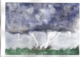
These
sub-vortices emerge from the base of a so-called ‘wall
cloud’ structure which forms beneath
some cumulonimbus storm clouds . This ‘wall cloud’ is a more or less vertical-
sided cloud growth, and, once formed, it rotates, sometimes quite rapidly. It is from the base of one of these wall
clouds that the multiple funnel cloud sub- vortices frequently appear, some of
which may then grow downwards to reach the ground and become tornadoes.
It seems most probable
that the ‘wall cloud’ consists of a
cloud, forming in the expanding and cooling
air of the potential circulating
flow part of the Rankine-combined vortex, that is, in the
circulational portion of the vortex surrounding
the central rotational core. This would fit with the straight sided
nature of the cloud, and its relationship to the funnel cloud of the central
core of the vortex. Because of the cloud and its associated heat of
condensation, the thermodynamic process of the inflow in the wall cloud portion
of the tornado cannot be isentropic, but must, instead, involve the heat engine
process.
2.7
Summary of the Main Tornado Model
Features.
 1.
The atmospheric vortex, in general, may start as a large gentle circulating
swirl having a central core in a state of fluid rotation, arising from
the rotational flow already present in a shear zone, or along a temperature
discontinuity, or in conflicting air flows beneath a convective storm
cloud. Then, conservation of angular
momentum brings about an initial speed up in the air flow into the vortex
towards its core. This speed up follows
from the relationship between vortex flow velocity, rotation rate ω, and
radial distance from the vortex centre
1.
The atmospheric vortex, in general, may start as a large gentle circulating
swirl having a central core in a state of fluid rotation, arising from
the rotational flow already present in a shear zone, or along a temperature
discontinuity, or in conflicting air flows beneath a convective storm
cloud. Then, conservation of angular
momentum brings about an initial speed up in the air flow into the vortex
towards its core. This speed up follows
from the relationship between vortex flow velocity, rotation rate ω, and
radial distance from the vortex centre
V/ r =
ω = constant
2. Once
the vortex core forms, the inflowing moist, but initially cloud free air,
expands linearly in the lower pressure towards the core centre. This flow expansion is isentropic, and so the
accompanying increase in flow velocity is large [see Sect. 2 above and the
isentropic relationships]. In this way,
small amounts of internal heat energy of the atmosphere represented by
temperature drops of only 1 to 5 degrees C, can, by means of the isentropic flow conversion, produce the
observed tornado wind speeds of 90 to 250 mph (40 to110 m/s).
3. As the air continues to flow into the newly
formed vortex, it expands isentropically and cools. When this cooling has
lowered the temperature of the air flowing into the vortex to its dew point, i.e. when the relative humidity of
the inflowing air reaches 100%, then
cloud condensation occurs, and the vortex` becomes visible, first as the
‘wall cloud’ and then as the core ‘funnel
cloud’ extending down from it. The
thermodynamic process in the outer, cloud free potential motion section of the
vortex is isentropic, while, in the wall cloud and the funnel cloud, it is the
heat engine process.
We may note here
that, while we have treated the vortex process as an isentropic flow energy
conversion or equalization of small
temperature differences between air parcels, we could also look at it from another point of view as
being, first the setting up of a pressure gradient between two air parcels of
slightly different air pressure ,
followed by the isentropic flow in response
to the pressure gradient . The end result is the same, namely, the smoothing
out of pressure differences by an isentropic expanding and cooling flow and
greatly increased flow speed.
4. If we recall that the isentropic process is
one of ‘no heat addition’, then, since the condensation of water vapour in the
inflowing air to form the funnel cloud adds its latent heat of condensation
(typically causing a rise in air temperature of 1 to 3 deg. C), the isentropic,
tangential wind speed-up must cease once
the funnel forms; and so the high speed- up phase of the tornado reaches
its limit. Any further speed up is by
the inefficient heat engine process, and this, as we have seen above in Part 1,
produces only much smaller wind speed- up of a few tens of meters per second.
(Two additional speed up mechanisms in the tornado base at the ground are
discussed below).
Therefore, in
this new model, the presence of a visible funnel cloud also signals that the
tornado has ended its high speed-up phase.
5. Some
additional speed- up at the ground, may, however, take place. At the ground,
surface friction alters the flow to permit
increased updraft in the so-called ‘corner
flow’ in which the inflowing tangentially swirling
air turns abruptly upwards to
spiral helically around the core up
towards the parent storm cloud above [9]. This abrupt turning requires
an abrupt acceleration of the flow velocity and a further drop in
pressure. However, the surface friction
also slows down the ground level tangential flow, permitting some inward cross
isobaric radial flow to set in. This frictional slowing of basic wind speed
must be subtracted from the vector sum of the tangential plus corner wind
speed.
In addition, multiple
‘suction vortices’, ‘satellite vortices’ or ‘sub-vortices’ may form with greatly increased wind speeds.
6. The above
points may perhaps be further clarified if the basic physical processes are
outlined from the equations of flow.
Euler’s equation for steady
streamline flow can be written as
dp = −ρ d(V2 /2 ) = −ρ
VdV (4)
which,
when integrated, becomes
∫ dp/ρ + V2 /2 = constant along
a streamline (4b)
(If we now treat the density
as constant, i.e. if we treat the fluid as incompressible, which is nearly the
case for low flow velocities, then the Bernouilli equation results
p/ρ + V2/2 = constant along a
streamline
The use of the incompressible
Bernouilli equation for a compressible fluid such as air, gives acceptable
numerical results for slower flow calculations ( less than about Mach 0.3), but its concepts
do not clearly show the fluid behaviour in adiabatic/isentropic flow, and so
the full isentropic equations for determining the thermodynamic quantities p,
ρ, T and V (Section 1.2 above) are
recommended even for low flow velocities.
7. In the case of a very dry atmosphere, where no
funnel cloud condensation would occur
even with very low pressures and large temperature drop on expansion, the isentropic equations would apply right up
to the sonic speed (330 m/s or just over 700 mph) and
the complete compressible flow treatment
of Abdullah [16] would apply.
Earlier researchers were unaware of any
physical limit to the velocity of tornados, and so Abdullah [16] introduced the
full compressible flow equations and proposed the sonic shock limit of around
313 m/s or 711 mph for tornado maximum speed.
With later observations that the top speed seemed to be about 135 m/s,
the problem of the physical reason for this speed limit arose again, and is
explained here via the condensation process which forms the tornado funnel
cloud and at the same time puts an effective limit to the funnel wind speed.
8. As to the hollow core
structure of many tornado funnels, this is explained by Kangieser [17] as a
centrifugal effect of the high speed
rotation in the funnel. The cloud
droplets are forced outward from the tornado core by centrifugal force to reach
an equilibrium radial distance, leaving
the core empty of cloud droplets..
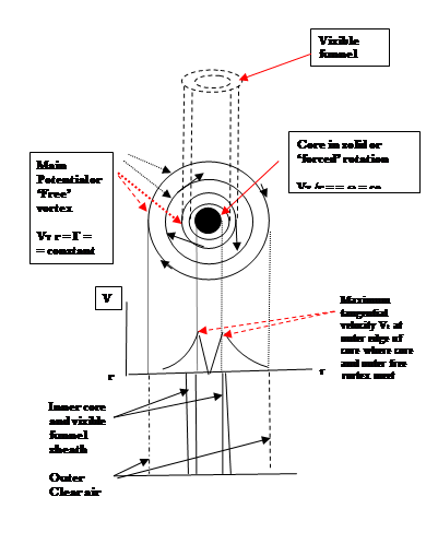 9.
The main elements of a tornado are depicted in Figure 8:
9.
The main elements of a tornado are depicted in Figure 8:
(1) a cloud free
rotational core in which V/r = ω = constant.
(2) a condensate
sheath surrounding the core which constitutes the visible tornado funnel cloud .This funnel or cloud sheath is highly
turbulent with small eddies about a
meter or so in diameter, and which
themselves are rotating and swirling helically around the hollow
core [18]. Flow transformations in this sheath are
non-isentropic and the heat engine process with only small velocity speed up
prevails.
(3) Outside the
funnel cloud or condensate sheath is a
much larger diameter, cloud –free, swirl area which is the Potential Vortex
or ‘free vortex’ region. The flow in it is in a state of circulation but is not
rotational. Flow transformations are
isentropic in this cloud- free region, and so this is the region of fastest
wind speed up, reaching a maximum tangential velocity right at the visible
funnel outer surface. From there inwards to the core the tangential velocity
decreases.
The whole
tornado, outer plus inner core comprises a Rankine- Combined Vortex.
Figure 8.
Rankine- Combined Vortex Model of the Tornado
2.8 A
Method of Estimating Tornado Wind Intensity Limits from Air Humidity
 Our analysis so far has shown that there are two distinct flow
speed-up mechanisms in tornados which produce very different wind speeds from
conversion of any given heat or temperature differential
ΔT. We can combine these two different flow processes to model the life cycle and intensity levels
of a tornado.
Our analysis so far has shown that there are two distinct flow
speed-up mechanisms in tornados which produce very different wind speeds from
conversion of any given heat or temperature differential
ΔT. We can combine these two different flow processes to model the life cycle and intensity levels
of a tornado.
First, as we have shown above, when the shear
flow at a temperature discontinuity in the
cloud free atmosphere develops into
a vortex, the inflowing air
accelerates isentropically, so that the resulting tangential velocity developed
in the outer cloud free portion of the
vortex is large even for small temperature
drops; for example a 1 deg
in flow temperature results in a
42.9 m/s tangential swirling wind speed
( i.e. 98 mph), 2 deg. C gives 60.7 m/s or 136 mph. The eventual
tangential velocity or intensity that is reached is limited only by the amount
of the temperature drop and pressure drop in the inflowing cloud-free air. The
vortex at this stag is invisible with no
funnel yet formed.
Table 2
Isentropic Tangential Wind
Speed Resulting From Various Atmospheric Temperature Transformations
To T1 ΔT(spread) Tangential
____________________________________________________________
303
˚K 302˚K 1˚C 42.9m/s 96.0 mph
303 301 2 60.7 135.7
303 300 3 74.3 166.2
303 299 4 85.8 192
303 298 5 95.8 214.6
303 297 6 105.1 235.1
303 296 7 113.5 253.9
303 295 8 121.3 271.5
303 294 9 128.7 287.9
303 203 10 135.7 303.5.
Notes
1. n = 5
2. co = 334 m/s = sound speed at
m.s.l.
Second, when the inflowing,
accelerating, expanding air in the vortex cools to the dew point Td ,
that is to say, when the relative
humidity R.H. reaches 100% and condensation of liquid cloud water takes place,
the tornado funnel cloud appears. This condensation releases latent heat of
condensation into the flowing air, and so
the isentropic speed up mechanism ceases in the cloudy funnel, and is
replaced in the funnel by the inefficient heat engine speed process.
Thus, the tornado intensity or speed up growth rate slows down
markedly when the visible funnel cloud forms and the tornado intensity slows or
stabilizes. .
The end result, is that a vortex velocity
limit emerges, consisting
of the
sum of the isentropic initial large flow speed increase plus the much
smaller heat engine speed increase after the funnel cloud
formation. For example, an isentropic
conversion of a 1 degree C of cloud free dry air inflow would give a flow
velocity of 43.9 m/s (96.0 mph) mph. The latent heat of condensation released
by the funnel cloud forming is, for example about 2 deg C: this added
heat, if converted to flow
velocity by the heat engine process,
would add only another 1.59 m/s or
3.6 mph, for a sum total limiting speed of 45.9 m/s or 102 mph.
Other combinations of clear and cloudy air speed up can be found in
Table 3.
Table 3.
Examples of Tornado Limit Velocity with Various Humidities (To – TD)
To Tcore ΔT TD To–
T D TD -Tc Isentropic Vel. Heat Engine Vel. Limiting Vel. (sum)
303 K 302 1 302.5 0.5C 0.5 30.3
m/s 1.29 m/s 31.6
m/s 71mph
303 301 2 302 1 1 42.9 2.58 45.5 102
303 300 3 301 2 1 60.7 2.58 63.3 142
303 299 4 300 3 1 74.3 2.59 77 172
303 298 5 299 4 1 85.8 2.59 88 198
303 293 10 294 9 1 128.7 2.61
131 294
To – Ambient warm
air mass temperature
Tcore – Cool core
temperature
ΔT - Total temperature
differential available for conversion into vortex tangential flow velocity
TD – Dew point of inflowing air mass ( A
measure of relative humidity, R.H.)
To – TD – Amount of cooling possible in
in-flowing clear air, until funnel cloud
forms or is entered by the inflow, and which is available for isentropic
conversion into high tangential increases in flow speed
TD – Tcore - Amount of cooling
possible inside funnel cloud and which is available for heat engine conversion
into much lower tangential increases in flow speed.
Isentropic Vel.
Flow velocity reached by isentropic conversion of temperature difference
in clear unsaturated air (see Table above)
Heat Engine Vel. – Additional Flow velocity added by
heat engine conversion of remaining temp difference between saturated air
inside funnel cloud and cool core temperature (see Table 1)
Speed conversion
factor: m/s x 2.2369 = mph
Since the heat engine component of the
speed up in the cloudy air in the funnel is small compared to the isentropic
component of speed up , a simple close approximation to the limiting, or top tangential
wind speed of a tornado, can be
calculated from the isentropic speed equation alone:
VT = n1/2
co [1 – TD/ To ]1/2
VT = 2.236 x 334 x [1 – TD/ To ]1/2
(mph) (1)
where TD
is the dew point and To is the temperature of the ambient air mass
surrounding the tornado and feeding into it.
Thus, on any
likely tornado day, from a forecast of the expected air temperature To and dew point temperature TD, the
use of this equation will give an estimate of the probable maximum tornado wind speed or tornado intensity for that
particular locality.
[This simple
tornado intensity predictor should be readily testable for validity against
historical tornado occurrence records and concurrent air mass temperatures and
humidity.]
Additional tornado funnel speed-up at
ground level.
When the tornado funnel cloud ‘touches down’
and reaches the earth’s surface, then
the surface friction slows the
flow and it turns a bit inward towards the core and across the circular
isobaric or pressure pattern, Fig. 9 .
This inflow leads
to the so-called ‘corner flow’ [9]
speed-up, where the radial, cross
isobaric flow into a tornado at the ground
must turn abruptly upward towards the vertical at the core boundary in
order to spiral up towards the storm cloud , and so must accelerates greatly.
Fig. 9. Surface friction turns the flow
Radially inward across the isobars towards
the core centre.
The corner flow and the so called ‘suction
vortices’ if present will locally add to
any general velocity predictions made from the dew point spread of Table 2. The slow down from surface friction
at ground level will of course subtract from the speed up effects.
2.9 A Unifying Vortex Element: The Flow
Condensation Discontinuity
We can now reconcile how a non- rotational, outer tornado region
fits smoothly into, and interacts with, an inner rotational core ,.
Once condensation and the accompanying release of latent heat into
the air takes place, the air flow where the air from the outer ‘potential
vortex’ enters the ‘forced vortex’ of the funnel is no longer smooth and
laminar, but becomes disordered and turbulent and its entropy increases significantly. It
also has become rotational, so that it is now in the same rotational
state as that which prevails in the vortex core of the Rankine combined
vortex. In this way, the now cloudy,
rotational air flow becomes smoothly incorporated into the already rotational
inner core flow.
In this way, we can integrate smoothly the circulating
non-rotational air flowing from the outer portion of the tornado, into the
vortex core which has opposite rotational fluid properties, so as to now explain
how the combined vortex in nature is a unified, stable, dynamic flow system.
To repeat, fluid angular rotation (ω) is necessary for stable
motion in the core of an atmospheric vortex, such as the Rankine-combined model
described. Since this necessary angular
motion cannot arise spontaneously in a fluid, its source in tornadoes, waterspouts, dust devils and the
like, is a matter of importance for understanding their motions, and hopefully,
even for predicting their occurrence and intensity. As we have stated above, some undoubted
initial startup fluid angular momentum
arises from shearing flow at the
interface between different local air
mass outflow velocities beneath storm cloud systems, from shear along a temperature inversion surface,
from friction induced shear flow in the atmospheric boundary layer at the earth’s surface, and so
on.
There is one additional rotational case that invites further
attention as to its role in tornadoes. This is the flow rotation that is needed
during the tornado funnel cloud formation and its growth from the parent wall
cloud towards the ground. This growth
towards the ground may be steady and take a few minutes to be completed. Even
more often, however, the funnel wavers in its downward growth, before slowly
retreating upwards to be adsorbed into the parent wall cloud from which it
emerged. The impression of some
imbalanced interplay of opposing physical processes is strong. A process that
involves both funnel cloud formation and the in situ emergence of the necessary rotation is the water vapor
condensation process that forms the funnel cloud. This condensation occurs in
the inflowing air as it enters the
vortex core. Here, the amount of cooling of the air in the vortex core at the
funnel cloud’s tip, is determined by the extent of adiabatic expansion and
consequent cooling in the core.
Now, if the moisture
content of the inflowing air, as evidenced by its dew point temperature, is higher than the vortex core temperature
at the growing vortex tip, then the inflowing air will be cooled below its dew point at the funnel’s tip, further cloud
condensation will take place,
and the tornado funnel cloud will
continue to grow and extend downward toward the ground,
On the other hand, if the dew point temperature of the air flowing
into the funnel tip core is lower than the core temperature, then no new
condensation will occur and the funnel cloud growth will stop. Depending on the
relative humidity of the inflowing air, the funnel cloud may even start to
evaporate and slowly retreat upwards to be re- adsorbed by the parent storm
cloud from which it earlier emerged when more moist conditions existed in the
air beneath the storm cloud.
In this way, the humidity of
the air beneath the wall cloud would appear to control the formation and growth
of the tornado funnel towards its touchdown at the ground, as well as
controlling its general intensity limits, and automatically furnishing the
necessary solid rotation right in the core itself.
-
3.0
Conclusions
 1. A fortuitous encounter with a very rare
type of mini-tornado which occurs under
very simple, fine weather conditions has yielded insights into its origin, structure and growth
which appear to be applicable to the
full scale tornadoes of convective
storms.
1. A fortuitous encounter with a very rare
type of mini-tornado which occurs under
very simple, fine weather conditions has yielded insights into its origin, structure and growth
which appear to be applicable to the
full scale tornadoes of convective
storms.
2. All tornadoes
require (1) a source for initiating a ‘solid’ rotational or vortical swirl motion, which becomes the tornado
core, and (2) an outer circulation of air flow around the rotational core which
is isentropically transformed into a high speed tornadic flow as it expands and
cools while flowing in towards the funnel and
(3) a continuous throughflow of air from a source, usually at the
ground, to a sink in the convective
storm cloud aloft. This vertical mass throughflow is sustained by the pressure
differential −Δp between ground level pressure and the pressure
aloft at the discharge level into the storm cloud.
3. In the case of the mini-tornado, the source
of the initial rotation or swirl is likely a weak wind flow past the shoreline
irregularities, and/or an instability wave on the temperature inversion surface
that forms over the cool lake in nearly calm, warm weather during the heat of
the day.
In the case of full scale, storm cloud
tornados, the originating swirl can be due to wind shear from flow past surface
topography beneath the storm cloud, or
from shear interaction within or between two cool outflows from beneath
large thunderstorms, especially beneath super- cell thunderstorms [8], or from
internal swirling flows within the wall cloud.
4. We now have explanations for (a) the
turbulent rotational sheath at the edge of the funnel cloud, (b) for the smooth
merger of the two types of vortex flow, namely the outer circulating flow with
the inner rotating flow, and (c) for the observed general speed limitation of
the tornado to around 300 mph or 135m/s
5. On any likely
tornado day, from a forecast of the expected air temperature To and dew point temperature TD, the
relative humidity appears to provide an estimate of the probable maximum tornado wind speed, or general tornado intensity,
for that particular locality and day.
This simple
tornado intensity predictor should be readily testable for validity against
records of historical tornado occurrence and concurrent air mass temperatures
and humidity.
6. We also have a
source for the inner core rotation of the tornado emerging in the flow at the
condensation discontinuity at the funnel cloud, where the inflowing air from
the outer potential vortex not only condenses some of its moisture to form the
funnel cloud but also releases rotational flow into the core, to thereby stabilize the vortex motion.
References
1. The
Tornado: Its Structure, Dynamics, Prediction and Hazards. Church, C.,
Burgess, D., Doswell, C. A., Davies-Jones, R., (eds.). AGU
Monograph 79, American Geophysical
2. Munson, Bruce R., Young, Donald F., and Okiishi, Theodore, H., Fundamentals of Fluid Mechanics, John Wiley & Sons, New York, 1990.
3. Doswell,
Charles, A.111, and Burgess, Donald, W. “Tornados and Tornadic Storms: A Review
of Conceptual Models”. In AGU Monograph 79, American Geophysical
4,5. Rossman, Fritz O., “Waterspouts and Tornados”, Weather, pp. 104-106, March 1956. Royal Meteorol. Soc., London [and in Monthly Weather Review, 48, p.351, May 16, 1920, “Observations on Lake Newcombe, Adirondack Mountains , N.Y”.].
6. : Tornado-genesis
by an Isentropic Transformation of Heat Differences into Wind Speed
7. Vonnegut, Bernard, “Electrical Theory of Tornados”. J. of Geophysical Res. 65, 1, pp 203-212, Jan. 1966.
8. Purdom,
James, F.W. “Satellite Observations of Tornadic Thunderstorms”, In The Tornado: Its Structure, Dynamics,
Prediction and Hazards. Church,
C., Burgess, D., Doswell, C., Davies-Jones, R., (eds.). AGU Monograph 79, American Geophysical
9. Lewellen,
W.S., “Tornado Vortex Theory”. In: AGU Monograph 79,
American Geophysical Union.
10.. Fujita,
T.T., and B.E. Smith, “Aerial Survey
and Photography of Tornado and Microburst Damage” in AGU Monograph 79, American Geophysical
11. Shapiro, A.H., The Dynamics and Thermodynamics of
Compressible Fluid Flow. 2
Vols., Wiley and Sons,
12. Prandtl, L. and O. G. Tietjens, Applied
Hydro- and Aeromechanics, Dover
Publications Inc.,
13. Lamb, Sir Horace. Hydrodynamics. Dover Publications Inc.
14. Brunt , David, Physical and Dynamical Meteorology.
15. Rankine, W. J., A
Manual of Applied Mechanics, , Charles Griffin,
16. Abdullah, A.J., “Some Aspects of the Dynamics of Tornadoes”. Monthly Weather Review, 83, 4, pp. 83-94, April 1955.
17. Kangieser, Paul C., “A Physical Explanation of the Hollow Structure of Waterspout Tubes”. Monthly WeatherReview, 82, 6, pp. 147-152, June 1954.
18. Golden, J, H., “The
Life-cycle of
19. Idso, Sherwood, B., “Tornado or Dust Devil: The Enigma of Desert Whirlwinds”. American Scientist, 62, 530-541, Sept. – Oct. 1974.
20. Bluestein, Howard A. and Joseph H. Golden, “A
Review of Tornado Observations”. AGU
Monograph 79, ( Ref. 3 above) pp.
319 -352. 1993.
22. By isentropic we mean ‘a thermodynamic process occurring without any heat energy input into or output from the system’; the energy for the change comes from the internal energy of the system. For example, in an isentropic flow acceleration of a gas, the internal energy supplies the work needed and this shows up as a drop in the gas temperature, pressure and density accompanying the flow velocity increase. Such an expansion is also called an adiabatic expansion. If the process is reversible, with the thermodynamic variables of pressure, temperature and density returning to their original values upon compression, then the process is not only adiabatic but reversible and so is isentropic. In the present work, we are concerned with dynamic flow expansions of gas rather than the static or volume expansions at zero flow. And so, even though the processes are probably not reversible, I have preferred to use the term isentropic process to describe the adiabatic flow changes since the appropriate unambiguous and convenient equations are the isentropic ones. The use of the term adiabatic might lead to some confusion that the process is a static volume expansion rather than a linear expansion accompanying a flow velocity increase.
Acknowledgement
I gratefully acknowledge the many years of essential encouragement from my dear wife, recently sadly deceased. She was the one to spot the mini-vortex which had so quietly and suddenly appeared. She was also the one who drew my attention away from fishing just in time for me to take in its astonishing essentials before it suddenly vanished. In spite of the difficulties and demands of advancing age, she never wavered in her conviction that I should pursue an explanation for this strange event.


Copyright © 2013
Bernard A. Power
Back to Main
Page