
Section 1
Linear (
streamline) Flow and Flow Power
Amplification
Section Links:
Section 2: Invention No. 1: A New Isentropic Air Motor and Clean Energy Source
Section 3: To be posted in near future
Abstract: This is is a brief
review of air flow fundamentals which lead to a way of enormously increasing the power of an air flow by efficiently
accelerating it. This leads to two new inventions for extracting the increased
flow power to do useful work. The new methods use ordinary air and involve no
fossil fuel heat input or noxious exhaust gases. If desired, the new air motor
can potentially provide a self-sustaining mode of operation ( Perpetual Motion).
Contents

1.1 Fluid Flow Principles: Linear (streamline) flow
1.2 Flow Losses and Inefficiencies
1.3 Flow Velocity Changes/
Acceleration and Pressure Changes
1.4 Flow Power Amplification: Accelerating the
Linear Flow of a Gas to Increase its Flow Power
1.5
Accelerating the Basic Linear Mass Flow
References
1.1 Fluid Flow Principles: Linear ( streamline) flow:
Before we describe the new acceleration and energy production process,
we need a few basic fluid flow principles. The general subject of air flow is a part of fluid mechanics
[Ref.1] which deals with both incompressible and compressible flows. Air is
compressible, so that its density is not constant but varies with the flow
speed V, the pressure p and the temperature T. The changes in air density
ρ with flow speed are quite small up to speeds of about Mach 0.3 (about 90
m/s), so that for low wind speeds, air is often treated as being incompressible
with the density ρ being taken as constant
(at about 1.2 kg per cu. m. at m.s.l.).With the density
constant, only the pressure and temperature changes need be considered. In this case, for the low speed incompressible
case, the two principal flow equations are the Bernoulli equation and the equation of mass continuity
which are as follows: ( units are SI, that is to say,
kilogram/meter/second units)
First, the Bernoulli
equation, which is related to the energy, is:
∫dp/ρ + ½ V2 = constant along a
streamline
(1)
For incompressible flow, this becomes
p/ ρ +
½ V2 = constant along a streamline; in energy units
(joules) (1a)
or p
+ ½ ρV2 = constant along a stream line; in pressure units (Pascals) (1b)
The second flow equation is the
Equation of Continuity of Mass:
ρ1 V1 A1 = ρ2 V2 A2 = dm/dt
= m-dot = constant ( kilograms/sec) (2)
where the subscript numerals refer to values of the density
ρ, velocity V and cross-sectional area A at different cross sections along
the flow path.
It is seen that Equation (2) represents the mass m of air
flowing per second (dm/dt), which in SI
units would be expressed as kilograms of air passing through any given area per second. Thus, a
reduced cross-sectional area A, means an increased velocity V and
vice versa.. The velocity
increase in a flow passing through a converging conical nozzle can thus be
formulated from (2) as
V2 = V1 [A1/
A2] [ ρ1/ ρ2]
(3)
From this we can see that, if the air density ρ were to be
constant, the velocity increase in a converging nozzle is inversely
proportional to the cross-sectional area decrease. This simplifying constant
density assumption
could apply for example to air
speeds of less than about Mach 0.3 ( 90 m/s) . Above that speed
compressibility becomes important and density changes must explicitly be taken into account through the isentropic relationships.
In an isentropic
flow [Ref. 1, 2, 3] the changes
in the thermodynamic variables of the
gas, i.e. in the pressure p, density ρ, temperature T, speed of
sound c, and flow velocity V, all take
place according to the isentropic relationships:
(p/po)(k-1)/k = ( ρ/ ρo)k-1
= T/To = (c/co )2
= 1 – (V/co)2
/n (4)
where n = 2/(k-1) and k is the ratio of specific heats. Expressed in
terms of the number of ways
n that the energy is divided ( n = 2/(k -1)) we also have
(p/po)2/(n+2) =
ρ/ ρo)2/n = T/To = (c/co )2 = [1 –
(V/co)2 /n ] (4a)
Thus, for
example, a drop in any one of pressure, density or temperature brings about an increase in
the flow velocity. The subscripted
values are for stagnation or zero velocity initial conditions. For air, the
value of k,
the ratio of specific heats ( k = cp/cv)
, has the value 1.4 . Here c is the speed of sound and co is its
stagnation ( no flow) speed.
As an example of
the magnitude of the isentropic effects, we may note that that at the flow speed of approximately 313 m/s ( i.e. at the sonic speed), the pressure will
have dropped by 47.2% to almost half an atmosphere, the density will have dropped by 37 % and
the temperature by 17%,. The isentropic values are readily available
from tables ( Ref. 1,2,3] or from various commercially available
computer programs for isentropic flow calculations.
Isentropic
velocity increases readily take
place, for example, in a converging
nozzle through which the flow is directed; the velocity reaches its maximum
value at the narrowest cross-section of the nozzle called the ‘throat’. If the
flow is then passed on
through a diverging nozzle, it will decelerate efficiently
without losses and drop back to normal
velocity, pressure and density value at the exit. The governing equations for compressible flow
of air in a nozzle are
the isentropic flow relationships as given in Eqns.4 and 4a plus
the equation of continuity of mass in Eqn.2

1.2
Flow Losses and Inefficiencies
The Bernoulli
equation, mass continuity equation and isentropic equations given above for linear flow all assume that
no flow turbulence, viscosity or friction is present This amounts to assuming that the flow is 100
% efficient. In practice, of course, some turbulence, heat flow
,viscosity and so on will be
present, but the losses can still with
care be kept as low as a few percentage
points. We also note that fluid acceleration
can quite easily be
made nearly 100% efficient; deceleration,
on the other hand, is more difficult to achieve efficiently, that is to say
without losses.[ Ref. 1]. We shall consider such accelerations in detail
shortly.
1.3
Flow Velocity Changes/ Acceleration and Pressure Changes
From isentropic considerations, we have [Ref. 2]:
dp = −ρV dV
Also, in incompressible flow the familiar
Bernoulli equation
p +1/2 ρ V2 = constant
gives the same
result, namely dp = −
ρV dV
Thus, an acceleration in flow velocity must result in a decrease
in pressure, whereas deceleration must bring about an increase in pressure.
We can now apply the above flow principles to explain several
interesting experimental problems.
Since an acceleration increases the kinetic energy of the flow, it
is natural to consider how the kinetic energy and power of a flow may be
increased and then extracted to do useful work.
Energy can be
added to a fluid in various ways. Heating a gas adds internal
energy and the
temperature and pressure are thereby raised. This process is the basis for the
operation of steam engines and internal combustion engines of all sorts, and
its thermodynamics and dynamics are well understood.
Another way of adding energy is to increase the flow velocity, so as
to add kinetic energy to the flow. This process is also very well understood,
for example in rocket
nozzle propulsion, gas dynamics, and so on.
Here we shall be concerned with adding kinetic energy and power to
a flow of gas ( specifically to air) and then extracting a portion of the power
increase to do useful work. The basic
mass flow of gas can be supplied
(1) by a vacuum motor or an air compressor ( and this leads to a first
invention to be described in Section 2, or (2) by the wind or a moving vehicle ( which
is the basis for a second invention to be described in Section 3).
1.4 Flow Power Amplification: Accelerating the
Linear Flow of a Gas to Increase its Power
The starting point here is a basic mass flow of air. This is supplied to a fluid in several
ways, for example by a “pull” or vacuum
source, a “push” or compressor source,
by the wind, or by the air flowing past a moving
vehicle on which the flow
apparatus is mounted.
Mass flow rate = ρ1 V1 A1 =
ρ2 V2 A2
= dm/dt = m-dot = constant
( kg/s)
(which
is the Equation of Mass Continuity ( Eq. 2) of Section 1.1 above)
The power of this basic mass flow at the source is usually low
since the flow velocity initially is low. The formula for air flow power is
P = ½ x (mass flow rate
) x V2
Thus a mass flow
of 0.5 kg/s at a velocity of 10 m/s has a power of P = ½ x 0.5 x 102
= 25 watts
In connection with supplying
and maintaining a given mass flow, it will be well to point out that any flow
of air from whatever source through an
apparatus will involve the pressure difference Δp = pin – pout across the apparatus from inlet to outlet; it
is this pressure difference which drives
and maintains the mass flow. In the case
of a vacuum pump flow source (Fig.1), the pressure difference will be that
between the ambient pressure at the inlet to the apparatus and the vacuum
pressure maintained at the vacuum pump. In the case of a compressor, it will be
the difference between the compressor exit pressure and the ambient pressure at
the apparatus flow exit port. In the case where the source of the mass flow is
the wind, the pressure differences across the apparatus from entrance to exit
are very much smaller, being just the dynamic or flow pressure of the air, p =
1/2 ρ V2 .
For example, a flow speed of V = 10 m/s will have a dynamic pressure of p = ½ ρ V2 = ½ x 1.2 x 102 = 60 Pascals. This is the pressure differential Δp across the apparatus from entrance port to exit port needed to maintain the flow of 10 m/s through the apparatus. Inefficiencies in the flow through the apparatus, such as turbulence and frictional losses will lower the pressure differential, flow speed, flow power and mass flow rate.
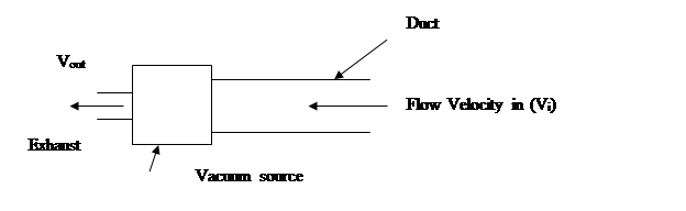
Figure 1. Linear “Pull” Flow Vacuum Motor
Also,
to give a specific example, a vacuum
source motor capable of delivering a pressure differential to sustain a mass flow of say, 0.074 kg/s,
would typically would require a
an input power of about 1700
watts to run it. However, conventional
vacuum pumps are inefficient ; for
example, the 1700 watts input cited would produce only 600 to 100 watts air
flow power, so that the vacuum pump efficiency would only be from 35% to about
6%.

1.5 Accelerating the Basic
Linear Mass Flow
This can efficiently be accomplished by passing the mass flow through a converging nozzle. The
nozzle can be of various shapes, such as conical, bell- shaped, parabolic,
etc., but all must be smooth walled.

Figure 2. Flow Acceleration in a converging/diverging
nozzle ( De Laval Nozzle)
The appropriate mass flow equation here is, again, the Equation of
Continuity of Mass
ρ1 V1 A1 = ρ2 V2 A2 = dm/dt
= m-dot = constant (2)
where the subscript numerals refer to values of the density
ρ, velocity V and flow duct cross-sectional area A at different cross
sections along the flow path.
It is seen that Equation (5) represents the mass m of air
flowing per second (dm/dt), which in SI
units would be expressed as kilograms of air passing through any given area per second.
Thus, a reduced cross-sectional area A, means an increased
velocity V and vice versa.. The velocity increase in a flow passing
through a converging conical nozzle can thus be formulated as
V2 = V1 [A1/A2]
[ ρ1/ ρ2]
(3)
If the density is constant, so that ρ1 =
ρ2 , then we have
V2 = V1 [A1/A2]
and
we see that the velocity increase in a
converging nozzle is inversely proportional to the cross-sectional area
decrease. This simplifying assumption of constant density applies to air speeds of about
Mach 0.3 ( 90 m/s) . Above that speed, the decrease in density with increasing
velocity becomes important for compressible fluids and must be explicitly be
taken into account
through the isentropic
relationships.
If the ratio of cross-sectional area is made large enough (that is
to say, if the nozzle
throat diameter is made small enough) then the throat
velocity can be increased to the
sonic speed (313 m/s). At this speed
the flow rate ( mass flow ) cannot increase further at the given throat diameter
and the flow is then said to be “choked”
[ Ref. 1,2,3].
It is interesting to calculate the increase in the flow power that this
acceleration to sonic speed has caused.
The power of the flow is
P = ½ (m-dot) V2 = ½ (ρ V A) V2 (8)
Let us take as an example, a converging cone of inlet area 0.0198 m2 (diameter
15.9 cm); and throat area of
.000998 m2 ( diameter
3.56 cm). Then, for an inlet flow of 10 m/s we have a mass flow of m-dot =
(ρ V A) = 1.2 x 10 x .0198 = 0.2376 kg/s., which will be the same at
inlet, throat and exit.
The power of the air flowing in at the inlet is then
P = ½ x 0.2376 x 102 = 11.9 watts.
However the power at the throat, where the velocity is now
sonic or 313 m/s and has the same mass flow of 0.2376 kg/s, becomes
P = ½ x 0.2376 x 3132 = 11,639
watts
or
an increase in flow power of 978 times!
Furthermore, since the process is isentropic, this all has
happened without any addition of energy from the outside.
What has happened is that
the internal energy of the gas itself has been lowered and has reappeared in
the form of increased kinetic energy of the flow.
All that is required here is that we maintain the mass flow by
maintaining the pressure differential from inlet to exit; the acceleration through the nozzle then takes
place automatically. There
is no input or output of outside of heat and so the process is
called isentropic. Isentropic nozzle acceleration of air flow is truly an
amazing phenomenon.
The natural question now is:
Q. Can we extract any of this
astonishing increase in flow power to do useful work? This will be answered in Sections 2 and
3.
References
1. Munson, Bruce, R.,
Donald F. Young, and Theodore H. Okiishi, Fundamentals
of Fluid Mechanics, Wiley and Sons,
New York, 1990.
2. Shapiro, Ascher, H., The
Dynamics and Thermodynamics of Compressible Fluid Flow, 2
Vols., John Wiley & Sons, New
York.1954.
3. R. Courant and K.O.
Friedrichs, Supersonic Flow and Shock Waves. Interscience,
![]()
Copyright Bernard A. Power, May 2011
Section Links:
Section 2: Invention No. 1: A New Isentropic Air Motor and Clean Energy Source
Section 3: To be posted in near future